Dynaflow, Inc.® has developed a new technique of testing materials using computer-controlled translating cavitating jets, DynaJets®, to determine the relative resistance of coated materials to cavitation erosion.
In accelerated cavitation erosion testing of thermoplastics or elastomers, a sample often heats up due to the repeated cavitation bubble collapse events, and this may lead to a material failure by combined effects of heating and cavitation. The new test method is developed to observe the effects of transitory cavitation on the coating in an effort to separate “heating” effects from stress effects on the materials. To accomplish this, a cavitation erosion facility was setup so that the cavitating jet nozzles could be computer controlled and translated over the test pieces at varying velocities and pressures. The nozzle was mounted on a carriage controlled by step motors so that the speed and position of the nozzle was precisely controlled. Also, desired pressure profiles could be achieved through a metering valve controlled by a programmable electric actuator.
The newly developed erosion test setup can control and vary cavitating region location, cavitating jet pressure, and cavitating jet speed during the test. The nozzle is mounted on an X-Y translation table powered by two step motors such that a prescribed trajectory can be programmed. A metering valve controlled by a programmable electric actuator is used to control the pressure to the nozzle. The pressure could be changed during an erosion test, while the jet is translated. The X-Y translation stage is controlled by a laptop through a RS-232 port, and a USB multi-functional data acquisition card is used to control and monitor the opening of the metering valve, which subsequently controls the nozzle pressure. Profiles of the pressure and nozzle translation speed can be controlled precisely during the erosion test through a control program. The top view of the system is shown in Figure 1 where the details of the X-Y table can be seen. The view of the nozzle and the sample setup in the test chamber can be seen in Figure 2.
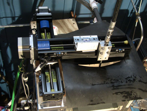 |
| Figure 1. Top view of the system showing the details of the X-Y table; the tank is covered by a flexible rubber sheet, through which the nozzle enters the water, to prevent water splashing. |
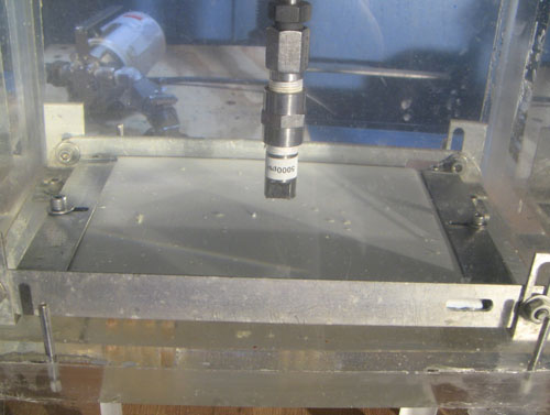 |
| Figure 2. Detailed view of the DynaJets® nozzle and sample, the sample is kept in place by a sample holder |
Panels coated with a commercial coating were used to establish a baseline. Test cases with selected translation speeds from 0.01 inch/s to 0.4 inch/s and pressures from 600 psi to 1,500 psi were conducted.
Figure 3 shows a picture of the erosion patterns on a test sample with pressures increasing from 700 psi to 1,100 psi at three translation speeds at 0.01, 0.025, and 0.05 inch/s. The figure shows clearly that, as expected, more erosion damage occurs at higher pressures and lower speeds.
In order to characterize the erosion, the erosion depths and widths were measured. Our previous work indicated that the trend of erosion width or depth can be characterized by a combined exponential and power equation (DFI erosion equation) in the form:
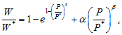 |
where W is the erosion width, P is nozzle pressure, W* and P* are characteristic width and pressure. This equation can be used to compare the behavior of different coatings, α, β, and k are fitting constants, which ideally should not vary between coatings.

Figure 3. Results of the erosion tests on a “verification” test sample with a blue rubbery coating. Each test is repeated 5 times to account for variability in the coating. The jet pressure varied from 700 psi (bottom of the picture) to 1,100 psi (top of the picture) with the jet translating from bottom to top at one of the three different translation speeds: 0.01, 0.025, or 0.05 in/s.


